Yesterday’s post about VPython simulation of the famous bicycle wheel demo showed that you can get the precession and nutation from a simulation that only includes forces. But this is still kind of mysterious, from the standpoint of basic physics intuition. Specifically, it’s sort of hard to see how any of this produces a force up and to the left, as required for the precession to happen.
I spent a bunch of time last night drawing pictures and writing equations, and I think I have the start of an explanation. It all comes down to the picture of rigid objects as really stiff springs– the grey lines in the “featured image” above. If we imagine a start condition where all the springs are at their relaxed length, then look a short instant of time later, I think I can see where the force is coming from.
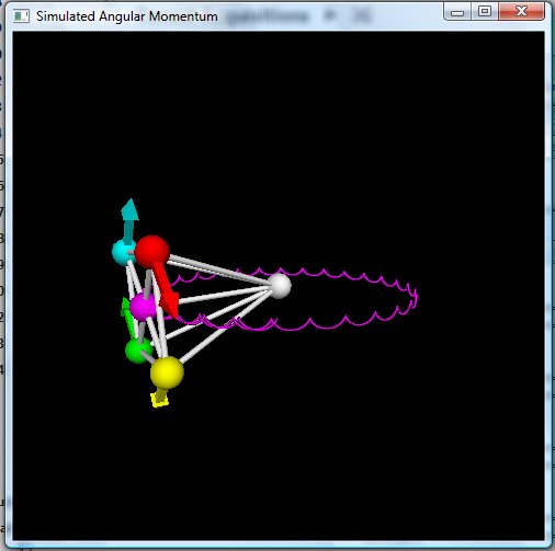
The two instants I want to imaging are shown schematically here– think of this as an end-on view of the rotating “wheel”:

All five of the balls (the four on the “rim” and the one at the hub) are subject to a downward gravitational force, and also have some linear momentum. If they start out exactly horizontal and vertical with the springs making up the spokes at their relaxed length, gravity is the only force that matters, and it’s indicated by short downward-pointing green arrows. The linear momentum for each ball is indicated by the reddish arrow (which deliberately doesn’t quite touch the ball, the usual convention I employ to try to avoid mixing up force and momentum arrows). The top ball is moving to the right, the bottom to the left, and so on.
A short time later, you end up with the situation on the right in the figure: each ball has moved a bit in the direction of its initial momentum, and also fallen down slightly due to gravity. You might be saying “Wait, the left ball actually shifted up from its initial position,” which is true, but that’s because the initial momentum was exactly vertical. It’s moved up by less than it would’ve without gravity, though.
Each of the “spokes” here has now stretched a tiny bit, and will thus be exerting a force pulling the ball toward the center. That’s a good thing, because it’s exactly the centripetal force you need to keep the balls spinning around in a more-or-less circular path (since I started the springs with no stretch, they’ll actually wobble in and out a bit as they go around, but it’s just cleaner to see what’s going on if we start with no forces). All four spokes have stretched by exactly the same amount, though, because the hub has also fallen by the same amount (you can convince yourself of this with half a page or so of equations; I’m not going to bother). All four spokes will exert exactly the same force, so they won’t have any net effect on the motion of the hub. So, this won’t get you the precession effect; but we knew that, because just having the spokes wasn’t enough in the simulation, either.
However, there are four more “springs” here, namely the braces stretching back toward the pivot point, which in this diagram would be straight back into the screen some distance from the initial position of the hub. If we imagine those four springs also started at their relaxed length, the motion of the balls makes them stretch, as well.
And while another half-page of equations can show it conclusively, I think you can see from the picture that these four springs do not all stretch by the same amount. On the right half of the figure, the distance from the center of the left ball to the center of the dotted outline showing the original position of the hub is smaller than the distance from the right ball to the original position of the hub, showing that the right spring will be more stretched than the left. And likewise, the top ball is slightly closer to where the hub was than the bottom is, so the bottom spring is stretched more than the top.
That means that the bottom and right braces will exert larger forces on the bottom and right balls. What are the directions of these forces? Well, mostly into the screen, but the bottom brace will also pull upward, and a little bit to the right. And the right brace will pull to the left, and a little bit up. The leftward pull of the right brace will be considerably bigger than the rightward pull of the bottom brace, so these don’t cancel each other out. There’s a down-and-left pull from the top brace on the top ball, and a right-and-down pull from the left brace on the left ball, as well, but these will be smaller than the pulls from the bottom and right braces.
If we carried this forward another step into the future, those forces would get communicated to the hub– the right ball would shift left as well as down, and the bottom ball would fall less quickly, compressing those spokes a bit beyond what they otherwise would be, which will then push the hub up and to the left. And the hub will push on the other two balls, so the whole thing moves up and to the left. But moving up and to the left is exactly what you need to get the precession effect seen in the simulation, and in the cool bicycle wheel demo.
Now, working all this out in detail, and carrying it forward for many more time steps is just a miserable mathematical grind. Which is why I simulated it on a computer in the first place, and why you’d be a fool to try to calculate this on paper without using angular momentum. But having confirmed from the simulation that this really does work with only forces, the two-time-step business above convinces me that I understand the origin of the precession and nutation at least in a qualitative way, which is more than good enough for a blog.
Thanks to you I might be on my way to understanding this, at least to the extent it can be understood. Did you mean to say that the left ball has a right-and-‘up’ pull from the left brace? I was expecting a right-and-down pull given what the other braces are doing.
Yes, that should be down, not up. I fixed it in the post, thanks for pointing it out.
Related question: is it possible to derive the force-multiplying effect of a lever without recourse to work, energy, or torque? As with angular momentum, it *seems* like it ought to be possible to work it out it strictly in terms of forces and the “rigid bodies are very stiff springs” approximation, but I’ve forgotten too much to work it out for myself.
(I ask this question because I once had a very frustrating conversation with someone who could not accept that force was not a conserved quantity.)
One way to do it would be with momentum balance.
Consider the level as rotating rigidly (i.e., no bending) about the fulcrum. The force at one end, applied to the mass at that end, induces a linear speed. That corresponds to an angular speed given the distance of that end from the fulcrum. Since the lever is assumed rigid, the other end experiences the identical angular speed, which can be converted into a (different) linear speed. The two linear speeds will be proportional to the distances from the fulcrum.
So now you can ask what mass can you put at that far end. You have to conserve momentum, so the products Mv at each end must be equal: M1 v1 = M2 v2, or M1/M2 = v2/v1. Since the linear velocities are proportional to the distances from the fulcrum (see above), you end up with Archimedes’ law, M1/M2 = d2/d1.
Hmm, that is effectively the same as the conservation-of-energy argument, only with momentum substituted for energy. I don’t think that would have satisfied the person who thought force had to be conserved (because of Newton’s third law, which, yes, I realize is a statement of conservation of momentum).
What I’m looking for is either an analysis in terms of forces and nothing else, or a demonstration that you just can’t do it without one of the conservation laws. I think there ought to be a way to do it, as I said, using the “rigid bodies are very stiff springs” approximation.